
INTELLIGENT PIGGING
MFL inspection/Intelligent Pigging/ Inline Inspection/ Corrosion Detection
- We at Athena has inspected more than 3000 Km Pipeline with Inline inspection tools ranging from 4” to 30”. This includes one of the longest LPG pipelines in the world, Jamnagar Loni Pipeline where we used Calier/MFL/TFI along with XYZ mapping technology and have successfully completed more than 40 dig verifications and all were found accurately. This is the biggest testimony of our technical and professional strength. We completed 12 pipeline segments ranging from 70 Km to 164 Km long and pipeline diameter ranging from 10” to 16”. In addition, we also completed inline inspection of Pipeline operators like GAIL India Ltd, GIGL, HPCL, BPCL, Reliance, Vedanta, OPAL. All these pipelines were completed with dig verification resulting 100% match within specified tolerance along with Fitness for Purpose including Corrosion Growth rate analysis.
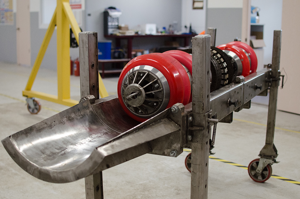
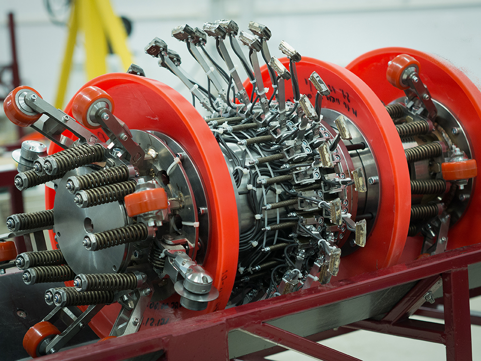
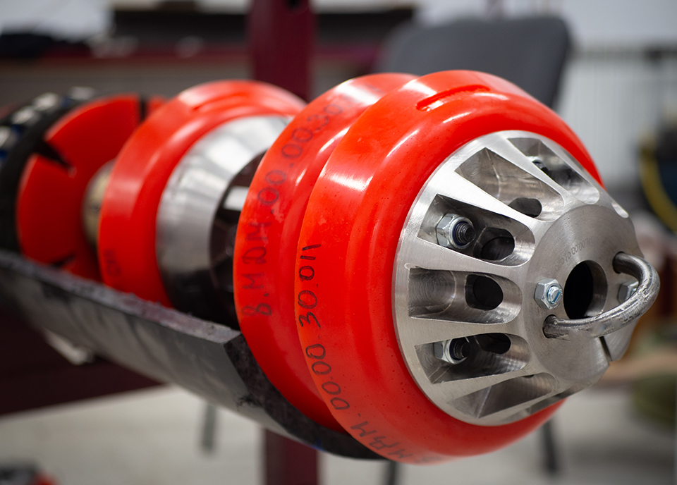
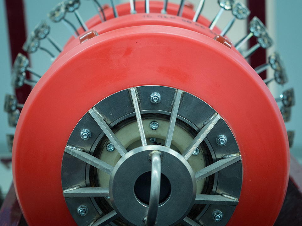
- Typically, most of the pipelines uses MFL (Magnetic Flus Leakage) technology for inspecting these pipelines for monitoring corrosion and any external damage to the pipeline. We offer range of tools for inspecting pipelines and also provide FFP (Fitness for Purpose) which means safe operation of the pipeline.
- The purpose of using these Intelligent pigs is to identify any type of Metal loss/Corrosion in the pipeline which can cause the pipeline to fail.
- We offer complete solution in association with our technology partner who provides us tool, and data analysis with reports. We help customer here to identify technology required, asses the condition of the pipeline, provide them with solution as to what is the best technology required to inspect their pipelines. We can support for the tolls ranging from 4” to 48”
- We have 20+ years of experience in running Inline inspection projects, tools, technology and related work, we also have experienced engineers with 15+ years of experience in running tools, data analysis and reporting as well.
- We also have technical support for providing Fitness for Purpose report after the Intelligent pigging is carried out and report is provided. We can provide FFP report based on Intelligent pigging report and data and can provide recommendation for repairs based on the intelligent pigging data.
- We also offer onsite dig verification services post Intelligent pigging report. This helps the Pipeline operators to verify the report provided by Intelligent pigging and compare result with actual finding on site. This helps customer to actually make a decision on the repairs to be carried out.
- We are based out of Vadodara and can provide with complete solution from feasibility study, pipeline cleaning, Geometry inspection, MFL/Intelligent Pigging, Onsite Dig Verification, FFP reports and repair recommendation.

Estimation of corrosion growth rate
High-resolution MFL tools collect data approximately every 2 mm along the axis of a pipe and this superior resolution allows for a comprehensive analysis of collected signals. Pipeline Integrity Management programs have specific intervals for inspecting pipeline segments and by employing high-resolution MFL tools an exceptional corrosion growth analysis can be conducted. This type of analysis proves extremely useful in forecasting the inspection intervals.
Other features that an MFL tool can identify
Although MFL tools are mainly used to detect corrosion, they can also identify other features for which they were not initially designed. When an MFL tool comes across a geometric deformity like a dent, wrinkle, or buckle, it creates a unique signal due to the plastic deformation of the pipe wall.
Crack detection
There have been cases where large non-axially oriented cracks have been discovered in a pipeline that was inspected using a magnetic flux leakage (MFL) tool. An experienced MFL data analyst can easily recognize a dent by the trademark "horseshoe" signal in the radial component of the vector field. However, what is not easily identifiable to an MFL tool is the signature that a crack leaves.