PIPELINE MAPPING SYSTEMS
Technological Principles
The DuctRunner™ Technology
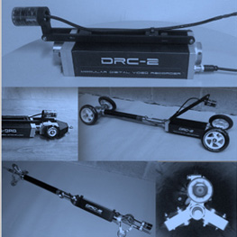
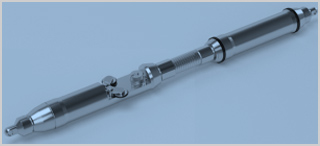
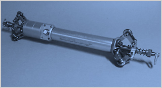
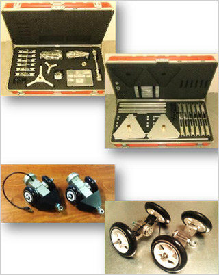
The Orientation Measurement Unit (OMU) contains all inertial sensors as well as a range of secondary sensors. The OMU is carefully calibrated to determine the alignment of each mechanically assembled sensor to within 0.01°.
The OMU is fully autonomous, i.e. it is battery powered and the data logged is stored internally during a measurement run. This eliminates the need to drag a data and/or power cable behind the system. Also, autonomy means that it does not need to be traced above ground as it moves through a pipe and thus can travel to any depth and underneath any obstacle (such as rivers, railways, highways, buildings etc.).
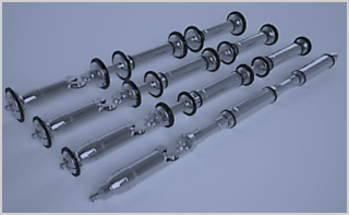
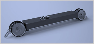
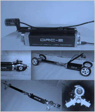
An application specific housing and centralizing system that typically contains the odometers to record the speed of travel.
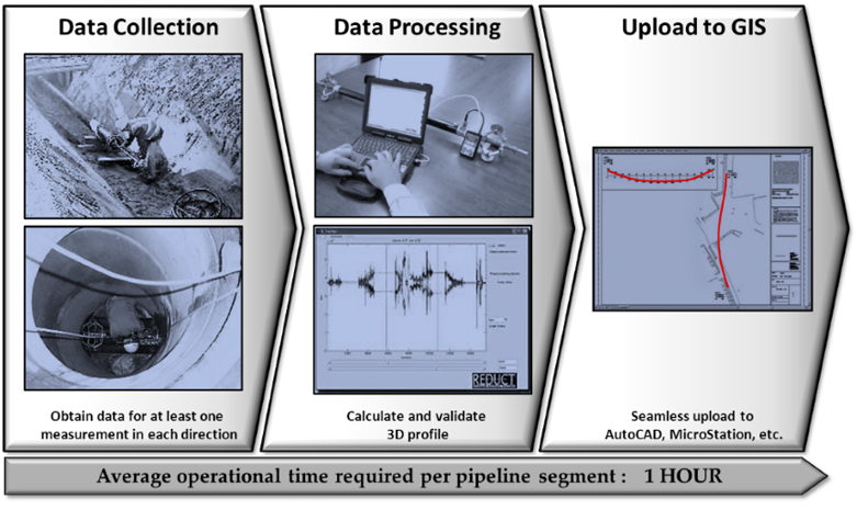
Proprietary X-Traction® and X-View® data processing software.
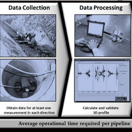
These software programs convert the autonomously logged data by the OMU and odometers to an accurate 3-dimensional line in the same coordinate system as the given coordinates at the entry and exit points.
The unique approach taken by Reduct means that it is not necessary to know the exact position of the OMU as it travels from entry point (A) to exit point (B). Rather, the software establishes where it has been after it is retrieved from the pipe.
Essentially, for each sample, the X-Traction® software calculates the angular change compared to the previous sample. The sample length is then derived from the odometer log. When the calculated vectors are placed in sequence, the path travelled is reconstructed, which is then linked to the known coordinates of A and B to obtain the final result in the chosen coordinate system. The resulting output can then be further processed to various forms of information.
System Accuracy
The calibrated accuracy of an OMU is 15cm in XYZ over a 500m distance between way-points assuming the following mapping conditions:
- HDD shaped track
- Temperature change < 5°C
- Pulling speed of 1.25m/s
- Flush pipe interior
- Perfect OMU alignment
- Acceleration/shocks < 2G
- Average of 4 valid runs (2 in each direction)
The above accuracy is equivalent to 0.03% or 1/3333. Note that pipe condition and operational handling can have a negative impact on the achievable accuracy of a measurement.
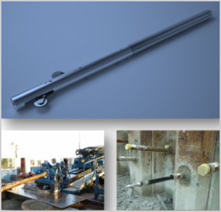
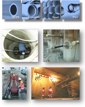
Applications
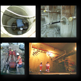
The DuctRunner™ technology can be deployed in any duct or pipe infrastructure that has pre-determined entry and exit points. The technology is not affected by electromagnetic interferences and can therefore be deployed in steel pipes, near live electricity cables, near railroads, etc. Because the probes operate autonomously, there is no limitation to measurement depth nor does it require above ground tracing.
In the course of a pipe's lifecycle, there are three opportune moments to collect positional data:
- during new installations
- when a pipe is rehabilitated
- during scheduled maintenance
In each of these stages the system output may be useful for different purposes.
Currently the most common applications are pipelines installed by trenchless technologies, anchors and freeze holes, upgrade of analog (or digitized) network data to digital data and high definition inclination assessment.
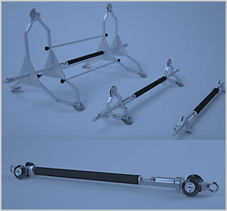
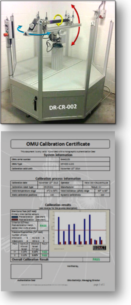
Calibration Procedure
Reduct pipeline mapping probes are manufactured and assembled using state of the art machinery and the best materials and components. The primary nine inertial measurement sensors are mechanically assembled such that they are placed as accurately as possible on the X, Y or Z axis of the probe. However, all mechanical assembly is invariably imperfect, i.e. the angles between the nine key inertial sensors are not exactly 90°. The objective, therefore, of the Reduct calibration procedure is to measure the angular errors and compensate them mathematically.
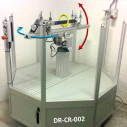
Over a period of about two hours, the DR-CR-002 calibration robot moves a probe through over 440 static positions and dynamic moves in an inclination range between -60° to +60° (red arrows) while rotating the unit 360° around its X-Axis (yellow arrow) and 360° around its Y-Axis (blue arrows).
A perfectly assembled system calibration data yields perfect sine curves. The probe's calibration data is compared to the perfect sine curves. Then, a series of proprietary algorithms will calculate mathematical adjustments until it finds the best fit to the perfect sine curves.
As a final check the probe's performance is tested on a fixed track. The probe is passed through the track in both directions and moving forward as well as backward. The repeatability of these measurements must be high: the spread (as a percentage of pipe length) on the XY-plane may not exceed 0.25% and in the Z-plane may not exceed 0.10%.
Operational Procedure